
 BLOG
BLOG
Tape measure vs. GPS in construction: when to upgrade your layout workflow?
A tape measure is still the right tool for straight pulls under about 30 m (100 ft), where nobody will question the number later. Past that distance, GPS RTK takes over. It keeps centimeter accuracy across the whole site and saves every point with coordinates and a timestamp.
You can usually spot the moment a tape measure runs out of road. The first three corners of a foundation go in clean. Then the diagonal check reads two centimeters long. The next pull comes back a fraction short.
This article covers where a tape still works, the four places it starts to fail, and what changes on site when RTK takes over, so you can decide if your next job is the one to switch.
Key takeaways
- A tape measure is still the fastest option for short, straight pulls under about 30 m (100 ft), like footing dimensions or anchor bolts off a trusted corner.
- On longer pulls, sag, uneven tension, and heat all push the reading the same way, so small errors add up to centimeters.
- RTK keeps centimeter accuracy at 10 m and at 500 m because the position comes from corrected satellite signals, not from a physical line across the site.
- A GNSS rover works in the design’s coordinate system, so a knocked stake doesn’t throw off the layout, and curves or offsets are calculated by the app.
- Every point you capture with RTK is saved with coordinates, a timestamp, and an optional photo, so a disputed measurement can be checked later.
Where tape measures still make sense, and where it starts to fail?
A tape is still the fastest tool on a 3-meter (10 feet) footing dimension, or when you’re marking anchor bolts off a corner you trust. The trouble starts on the long baselines, the knocked stakes, the curved alignments, and the measurement that gets disputed two weeks later.
Evaluate your recent projects: if you’re consistently exceeding the range of physical tape, as in scenarios above, then GPS might be the optimal tool for your workflow.
1. Accumulating error over long distances
A tape is forgiving on short pulls. The longer the pull, the more small errors have time to add up:
- Steel tape sags in the middle. The longer the span, the deeper the sag, even when you pull hard.
- Pull tension varies between operators.
- Steel expands with heat. A tape calibrated at 20 °C grows by about 12 mm per 100 m for every 10 °C rise, so after a morning in the sun, it reads short and puts layout marks too far out.
Each of those errors is small on its own. The problem is that each one repeats the same way on every pull. A sagging tape reads long every time, and a hot tape reads short every time. These errors don’t cancel out over a long run. They add up with every tape length.
That’s why the diagonal at the start didn’t close. Two long pulls, each off by about a centimeter in the same direction, put the corner several centimeters from where the design said it should be.
The alternative: RTK GNSS
A quick word on terminology
GPS is what most field crews call it, but the technically accurate term is GNSS, the satellite-positioning family that includes GPS alongside Galileo, GLONASS, and BeiDou.
RTK is the real-time correction layer that takes GNSS from meters of accuracy down to centimeters. The rest of this article uses GPS, GNSS, and RTK the way the industry does, often interchangeably.
With GNSS, nothing is being physically pulled across the gap. The position comes from satellites overhead, corrected in real time. So a point 50 meters (164 feet) from the base lands as cleanly as one 5 meters (16 feet) from it. Sag, tension, and heat have nothing to act on.
Under a clear view of the sky, RTK typically holds about 1 cm horizontal and 2 cm vertical accuracy, according to guidelines from the U.S. National Geodetic Survey (NGS).
A GNSS RTK setup is three pieces working together:
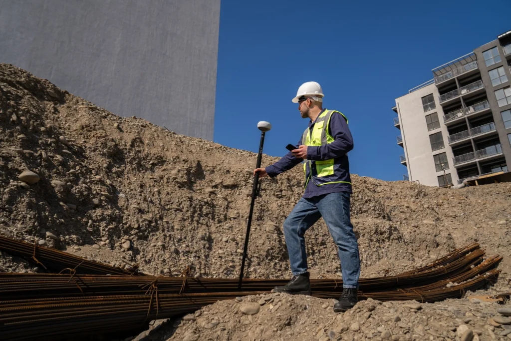
- A rover: the receiver that the field engineer carries on a pole.
- A correction source, which can be one of three: a second receiver set up nearby as a base station, an NTRIP service that streams corrections over a mobile connection from a network of Continuously Operating Reference Stations (CORS) and Emlid Corrections, built into the receiver.
- A surveying app on a phone or tablet, where the design file lives, where the rover connects, and where points get captured.
With Emlid Corrections, the rover gets 1–2 cm accuracy over the internet, with no base station to set up and no NTRIP credentials to configure. The first year is included on eligible Reach devices.
2. No reference to the design model
A tape measure depends on the stake or corner you’re measuring from.
If that reference moves—bumped by an excavator bucket, knocked over by a trade walking past, or set up wrong in the first place—every measurement that came off it is wrong too. The crew often finds out after the next one breaks.
RTK doesn’t have that dependency: the corrections come from a base receiver on a known control point, or from a network correction service, and the rover finds its position in the design’s coordinate system regardless of what happens to the stakes in the work area. If a corner gets knocked, the rover still knows where the corner should be.
Related reading: RTK corrections delivery method explained: how to choose the right setup?
3. No record
A taped measurement only exists in the moment it’s taken. Maybe someone wrote a number on a worksheet, maybe not. When the measurement gets questioned later—by an inspector, the GC, or another sub on the same site—there’s no record to compare against.
Every point collected with a GNSS receiver carries its own evidence: coordinates and a timestamp are saved automatically in a survey app, so the field engineer can add a description, a feature code, or a photo on top of those. All of it lives in the project file on the phone, and the office can pull up the same project in a browser anytime they need to.
So if a question comes up two days later about where the corner of the slab was, the answer is already there, including a picture of the stake in place.
That’s exactly what Reach GNSS receivers and the Emlid Flow app work. They allow the whole workflow to run on the phone that the team already carries. And on the office side, you can count on the Emlid Flow 360 cloud platform: every survey project can be opened from a browser, kept in sync with the field as it works.
4. Curves, angles, and offsets
A tape measure is built for straight-line distances. As soon as the layout includes a curve in the curb, an offset from a property line, an angle that isn’t 90 degrees, or an intersection of two design lines, the tape is doing geometry the field crew has to solve in their head.
That math is slow and error-prone, and it shouldn’t be the field crew’s job during a layout.
RTK GNSS with COGO or coordinate geometry tools does the geometry. The COGO functions in Emlid Flow compute offsets, bearings, and intersections from the design. The crew puts the rover where the screen says.
Take a row of foundation piers along a wall set 1.5 m off a property line that runs at 7 degrees from due north. With a tape, the crew has to compute each pier’s coordinates from the property corner, account for the angle, and pull two measurements per pier.
With COGO, the crew loads the property line and offset, taps each pier in the design, and the screen navigates to it directly.
Some points can’t be reached with a tape or a rover at all, like a manhole across a busy road or a corner behind a fence. The Reach RS4 Pro handles these with photo measurement: its built-in cameras capture the area, and you pick the point from the images.
Which layout tasks can RTK actually hold?
RTK accuracy only matters when you compare it with the tolerance the job requires. Most site layout has more room than people expect. A few tasks are tighter than RTK can reliably hold, especially in the vertical, and those still need a level or a total station.
| Layout task | Tolerance the spec requires | Right tool |
|---|---|---|
| Rough and fine grading to design elevation | – Typically set by the project spec in hundredths of a foot. – Comfortably inside the RTK envelope. | RTK GNSS |
| Building corners and gridline offsets | – Set off surveyor control. – Tight gridwork can call for more precision than RTK holds. | – RTK GNSS for initial placement. – Total station where gridwork is tight. |
| Foundation plan position (horizontal) | – ACI 117: ±50 mm on the as-cast edge for foundations 2.4 m or larger. – The greater of 13 mm or 2% of the specified dimension for smaller foundations. | RTK GNSS |
| Foundation top elevation (vertical) | – ACI 117: +13 mm / −50 mm. – Asymmetric, so the plus limit is about four times tighter than the minus limit. | – RTK GNSS against the −50 mm limit. – Level or total station to confirm the +13 mm limit. |
| Curb, drainage, and utility alignment | – Horizontal alignment well within centimeter accuracy. – Invert grades are usually the controlling tolerance. | – RTK GNSS for alignment. – Level or total station for invert grades. |
| Anchor bolts | – ACI 117 and AISC 303 (harmonized): ±1/4 in (6 mm) to ±1/2 in (13 mm) on each bolt’s centerline, depending on bolt diameter. – ±1/2 in (13 mm) on top-of-bolt elevation | – Templates – Total station |
| Structural steel and facade work | – Millimeter level, often with the sky blocked by the structure. | Total station |
| As-built capture and progress documentation | – Matches the placement tolerance of the element being recorded. – No separate, tighter requirement. | RTK GNSS |
Sources: ACI 117-10 Specification for Tolerances for Concrete Construction and Materials (preview); anchor bolt tolerances: ASCC Position Statement 14 and For Construction Pros on ACI 117 and AISC 303 harmonization.
State departments of transportation already write GNSS into their construction contracts. An Indiana DOT special provision requires the contractor to supply a survey-grade GPS rover with 0.1 ft horizontal and vertical precision for the department’s own engineers to use on the project.
Where a total station is still the right tool
RTK covers most layout on an open site. Three situations still call for a total station, and a robotic one is usually what construction crews reach for.
Millimeter tolerances. Anchor bolt groups, structural steel, and facade work are measured in millimeters. A total station measures angles and distances directly from a controlled setup. That’s why it stays stronger for precise relative measurements, according to Global GPS Systems’ comparison of the two tools.
Obstructed sky. GNSS needs a clear view of the satellites. Next to tall walls, under tree canopy, or around cranes and steelwork, signals get blocked or reflected before they reach the antenna. All-band tracking helps here: the receiver has more signals to work with, so it gets a fix faster and keeps it longer in urban sites and under canopy. It doesn’t remove the limit, though. When the sky is mostly blocked, a total station only needs a line of sight to the prism.
Repeatable work from a controlled setup. Monitoring points, deformation checks, and gridwork that has to match to the millimeter from day to day all depend on measuring the same way from the same known setup. A total station is built for that.
In practice, most crews don’t choose one tool over the other. They use RTK for production work, like grading, site layout, utilities, and as-builts, and a robotic total station for the points they can’t afford to miss. GNSS can also set the site control that the total station then works from.
Related reading: Volume measurement: total station vs drone mapping
RTK stakeout vs tape measure: what actually changes on site?
With RTK GNSS, the geometry moves out of the crew’s head and into the software. Four Emlid tools work together for this workflow:
- Reach RX2: all-band RTK GNSS rover with tilt compensation.
- Reach RS4 Pro: all-band RTK GNSS receiver with tilt compensation and dual cameras for AR stakeout.
- Emlid Flow: iOS and Android app for stakeout and capturing field data.
- Emlid Flow 360: cloud workspace where the office and the field share one project in real time.
1. Navigation to design points
You open Emlid Flow on a phone and load the design file. Whatever the design has in it, like building corners, curb stations, drain locations, or slab edges, shows up as points on the screen.
Tap the one you want, and the app gives you a direction and a distance from where you’re standing. Walk toward it. The numbers shrink as you go. When you’re within tolerance, the phone beeps, and that’s where the mark goes.
With the Reach RS4 Pro, stakeout can also be visual. AR stakeout overlays the design on the live camera view, so you see where the stake goes on the ground instead of only following coordinates on a map.
It’s a small change in workflow that ends up being a big change in what the day feels like. The crew stops carrying the layout in their heads. There’s no more “did we account for the offset?” or “is this corner right?”—the corner is right when the screen says it is.
2. Accuracy that holds regardless of distance
The Reach RS4 Pro is rated at 7 mm + 1 ppm horizontal and 14 mm + 1 ppm vertical in RTK. The ppm (parts per million) part is the distance term: about 1 mm added for every kilometer between the rover and the base. At 500 m (1,640 ft) from the base, that’s half a millimeter.
Distance still matters, but not the way it does with a tape. A tape picks up sag and heat error on every pull. RTK adds a small, predictable amount that stays well inside construction tolerances across a normal site.
Tilt compensation removes the need to level the pole at every point. The receiver knows how it’s oriented and corrects the position itself. This saves time on sloped ground and helps in tight spots, like building corners or against footings, where a plumb pole doesn’t fit.
The correction adds a small error that grows with the angle. At a 30° tilt with a 1 km baseline, the RS4 Pro still gives 18 mm precision. For tight tolerances, keep the pole close to vertical. Read more about how IMU tilt compensation works.
3. Digital record by default
Every point captured during layout saves to the project file automatically, with coordinates, a timestamp, a description, and a feature code. The field engineer can also take a photo in Emlid Flow at the moment of capture, and it stays attached to the point. The crew doesn’t fill out a separate log.
With Emlid Flow 360, that record syncs between the field and the office as the work happens. A PM can watch the layout being staked, in the same coordinate system as the design. So when the office asks two weeks later which side of the stake the rebar was set on, or the GC asks where a corner ended up, the answer is already in the file.
The same record supports QA/QC workflows in construction and as-built surveys with GNSS.
Want to see how it works in practice? Here’s a video on truly real-time field-to-office data sync with Emlid:
Related reading: Minimize construction site visits: how to support your field crew remotely
What does the switch actually cost?
The tape measure itself is cheap, and that’s the easy half of the calculation.
The harder half is what happens when a measurement is wrong: the rework, the surveyor callout when the crew hits geometry a tape can’t handle, and the time the foreman spends re-checking measurements that should have been right the first time.
Rework is a big number across the industry. The Construction Industry Institute (CII) found that direct field rework averages about 5% of total construction value across 144 industrial projects, and reaches 12.4% at the 90th percentile, according to a summary of the CII IR-153 dataset. Surveyor return visits add up too.
Market pricing for re-staking typically runs $1,000 to $5,000 or more per visit, depending on the region and the scope.
Take a forming sub pouring curb along a property line that runs at a slight angle. The offsets aren’t checked beyond what a tape can do, and two sections end up in the setback. The fix is breakout, re-stake, and re-pour: crew time, materials, and a hold on the rest of the pour schedule.
On the other side of the calculation is the equipment:
On the other side of the calculation is the equipment:
- Reach RX2: a one-time purchase for the rover.
- Emlid Flow: the free plan covers receiver setup, point collection, and stakeout, with unlimited projects and team collaboration. The Pro plan adds CAD and DTM files, localization and COGO tools, linework, and reports. It’s billed per user, and you can try it free for 30 days.
- Emlid Corrections: the first year is included with Reach receivers. After that, you can renew for one year or lock in three years at a lower yearly rate.
- Firmware and software updates: free.
A project manager weighing the spend should compare the cost of one rework event over the year with the price of the receiver. A single re-excavation, a missed inspection, or a dispute that costs a day on site is often enough to cover it.
Related reading: Where construction loses profit and how GNSS helps and Grade control guide: cut and fill
Who can use RTK and how quickly?
The most common objection from a project manager hearing about RTK is that it sounds like surveyor work. Some of it is, but a lot of routine layout doesn’t have to be.
Who is allowed to do layout depends on the jurisdiction and the contract, and the rules aren’t the same everywhere. California, for example, requires construction staking to be done by a licensed land surveyor or civil engineer. Other states don’t require a license for staking improvements unless the work relates to the property boundary.
The contract can set its own rules too. Many construction contracts include a layout and field engineering clause that requires all layout and earthwork grades to be done by a licensed civil engineer or land surveyor approved by the owner and the architect. Before you hand layout to a field engineer, check two things: your state licensing board and the project’s general conditions.
Where the rules allow it, routine layout like building corners, curb stations, drain locations, and slab edges can be run by a field engineer with a Reach rover and a phone. The field workflow is plain: load the design, walk to the arrow on the screen, and place the mark. The receiver also removes some of the setup steps crews usually deal with. Tilt compensation on the Reach RX2 is factory calibrated, so there’s no recalibration in the field, and the receiver typically gets an RTK fix in about 5 seconds.
Matt Kippelen, a field engineer at Menard USA, uses the Reach RX2 with Emlid Flow for standard layout and navigation. He says the whole setup is easy to learn:
“It’s easy to train new engineers on, which matters for us because our use case is a bit different. We’re a construction company using Emlid to survey points on active job sites, and the users are field engineers—often younger people who are early in their careers. It’s not seasoned surveyors with decades of experience.”
A licensed surveyor is still needed for the work that requires the license:
- The certified record the GC’s office needs at closeout.
- The control points the surveyor sets before the subs arrive.
- Any work where the jurisdiction names a licensed surveyor by statute.
The shift is about keeping the surveyor focused on that work, while the field engineer handles the rest.
Related reading: RTK GNSS for subcontractors and specialty contractors
How do you get set up?
Getting set up is simpler than most project managers expect. A Reach RX2, a phone running Emlid Flow, and Emlid Corrections are enough to start running layout on the next job. You don’t need a base station or a third-party NTRIP account.
Not sure which setup fits the jobs you run? Talk to an Emlid regional manager about your sites, the tolerances you work to, and whether the RX2 or another Reach receiver is the better fit.
Frequently asked questions
Under a clear view of the sky, RTK typically reaches about 1 cm horizontal and 2 cm vertical accuracy. Many manufacturers rate their receivers at 1 cm + 1 ppm horizontal and 2 cm + 1 ppm vertical, according to guidelines from the U.S. National Geodetic Survey (NGS). The Reach RX2 is rated at 7 mm + 1 ppm horizontal and 14 mm + 1 ppm vertical. In both cases, vertical error is about double the horizontal. That’s why tight elevation checks, like the top of a foundation or pipe inverts, often go to a level or a total station.
For most layout, yes. Grading, building corners, curbs, utilities, and as-builts all fit within RTK accuracy. A total station is still the right tool for millimeter tolerances and for work where buildings, steel, or tree canopy block the sky. Most construction crews run both: RTK for production work and a robotic total station for the points they can’t afford to miss. That’s standard practice, not a compromise.
No. ACI 117 and AISC 303 use the same anchor bolt tolerances: ±1/4 in (6 mm) to ±1/2 in (13 mm) on each bolt’s centerline, depending on bolt diameter, according to For Construction Pros. That’s tighter than RTK can reliably hold. Set anchor bolts with templates and check them with a total station.
It depends on the state and on the contract. Some states, like California, require construction staking to be done by a licensed land surveyor or civil engineer. Others only require a license when the work relates to the property boundary. Separately, many contracts require all layout and earthwork grades to be done by a licensed civil engineer or surveyor approved by the owner and the architect. Check your state licensing board and the project’s general conditions. Either way, the certified closeout record and the project control points stay with the licensed surveyor.
The field workflow is short. The RX2’s tilt compensation is factory calibrated, so there’s nothing to calibrate in the field, and the receiver typically gets an RTK fix in about 5 seconds. From there, the crew loads the design in Emlid Flow, walks to the arrow on the screen, and places the mark. Setting up project control and coordinate systems is a separate skill. That work usually stays with the surveyor or an experienced field engineer.