How to run fast and error-free underground utility projects with GNSS
Underground utilities are a part of a construction project you can’t easily revisit once they’re covered.
A sewer pipe with the wrong invert elevation or slope can mean reverse flow or a failed inspection. If the as-built record doesn’t match the actual install, a future excavation can strike the pipe. The fix in any of those cases is the same: dig it up.
Modern GNSS gear changes the math. With GNSS receivers the project team can stake the alignment, verify invert elevations as the pipe goes in, and capture the as-built before backfill, without a survey crew on standby at every step.
Three GNSS moments matter in a utility and wet utility install: layout, grade verification, and as-built. Each one calls for a different approach.
This article walks through each one—part of a series on how construction subcontractors win with GNSS.
The wet utility stakeout and grade challenge
Traditional offset staking on a utility job goes like this: a surveyor lays out stakes for manholes, pipe centerlines, and offsets, then leaves.
The crew works from those stakes for the day. If a stake gets bumped, knocked over, or buried by spoil, work pauses until the surveyor is back. On a multi-week run, that’s a lot of waiting.
Grade checks may be one of the most challenging issues, because they don’t get checked enough:
- Gravity sewers and storm drains rely on a continuous slope from upstream to downstream: every section needs to sit at the right invert elevation.
- The pipe has to tie into existing manholes and laterals at the right depth.
Set the invert wrong, and the next section either has the wrong slope or doesn’t connect cleanly. With conventional tools, checking each pipe section’s invert takes time. So it gets spot-checked.
The crew installs a few pipe sections, the surveyor verifies the grade at the connection points, and the stretch in between is left to the pipe laser and the operator’s intuition. In most cases, that suffices. However, the hidden cost of those gaps manifests only once the trench is buried.
The software and products
The workflows in this article are built around:
- Reach RX2: pocket-sized RTK rover that pairs to your phone or tablet over Bluetooth. Perfect for fast mobile GIS and mapping tasks where internet connectivity is available.
- Reach RS4 (and Reach RS4 Pro): professional pole-mounted receivers that connect to Emlid Flow for survey workflows in the field. Works over both NTRIP (internet) and radio, making it ideal when you don’t have cellular coverage on site.
- Emlid Flow: the field app–it runs on the surveyor’s phone or tablet and handles stakeout, point collection, and as-built capture.
- Emlid Flow 360: the cloud workspace for the office side–importing design files, setting up coordinate systems, and managing teams.
Stage 1: Pipe alignment layout
When working with GNSS for utility and wet utility, layout comes first. The job is to mark the design on the ground: manhole centers, pipe centerlines, and offset references. The marks have to be accurate enough that the excavator and pipe crew can work from them for the next stretch of trench.
For corrections, a Reach RX2 rover connects to an NTRIP service over the internet or receives RTK corrections from a local base. NTRIP works when there’s cell coverage and a Continuously Operating Reference Station (CORS) or paid service close enough to deliver the accuracy required.
On sites beyond cellular range, a Reach RS4 set up on a known control point and broadcasting over LoRa handles the base role. The rover picks up corrections the same way—the correction source changes, the workflow doesn’t.
Related reading: RTK corrections delivery method explained: how to choose the right setup?
Working from design files
The design reaches the field engineer in whatever format the office prepared. For utility and civil construction projects, this is often a CAD drawing exported as DXF containing pipe alignments, stationing, manhole locations, rim and invert elevations, and lateral connection points.
For utility alignments or as-built data coming from GIS platforms, the project may instead be exported as KML or CSV.
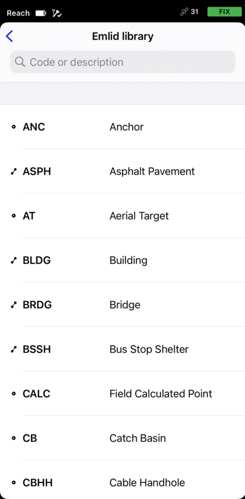
The project manager or survey manager imports these files into Emlid Flow 360, sets up the coordinate system, and adds the survey code library, imports additional data like surfaces in the office before the field crew arrives on site.
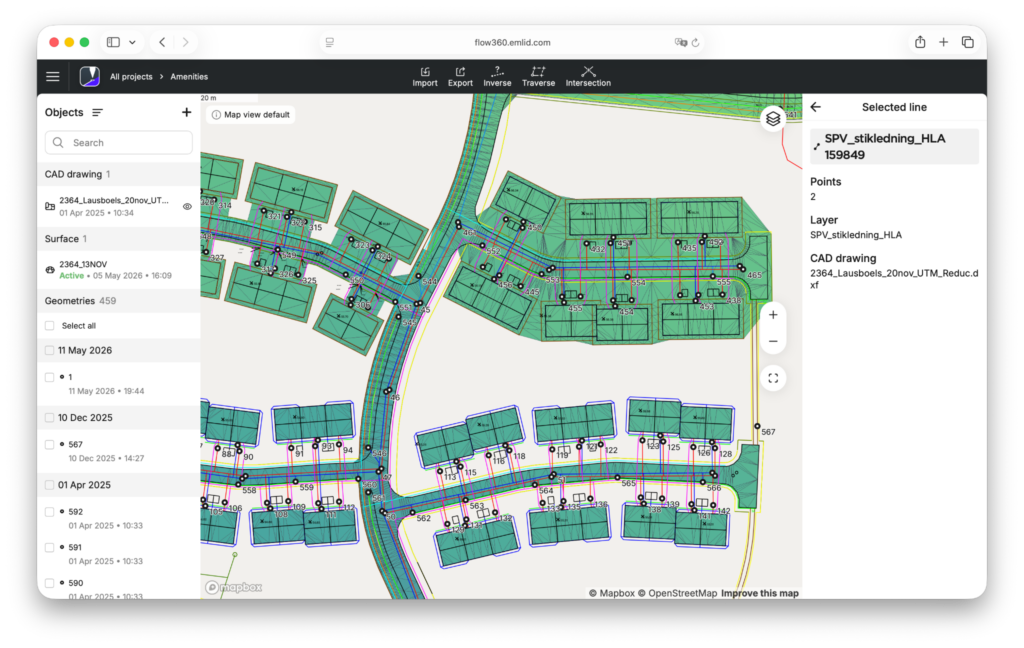
The project syncs to Emlid Flow, so the field engineer arrives on site with the latest design data already loaded.
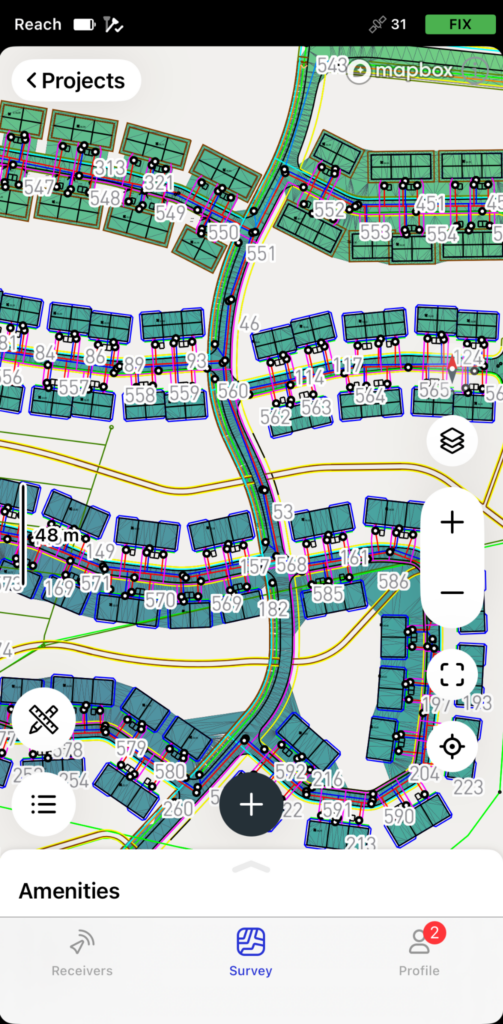
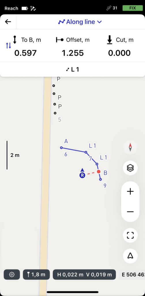
Then, the surveyor opens the stakeout view, selects the needed object, and walks toward it. The app displays real-time distance and direction guidance, along with audible feedback when the rover reaches the required tolerance.
Each stakeout point carries its design metadata automatically. This may include descriptions such as manhole center, pipe end, or offset stake at a specific station:
- In DXF workflows, Emlid Flow reads this information from layer names or block attributes.
- In CSV, KML, and SHP workflows, the descriptions are imported directly from the description column: no manual entry in the field.
Staking manholes and pipe ends
A stake on the centerline doesn’t survive the excavator: the first bucket through the trench takes it out, and the pipe crew loses its reference at the worst possible moment.
That’s why offset stakes go in first. They sit 1.5 to 3 meters off the centerline—far enough to one side that the dig leaves them alone, close enough that the pipe crew can measure straight off them once the trench is open.
In Emlid Flow, the workflow is the same for every feature: a stake on the design point first, then a second stake at the offset—perpendicular to the alignment, with the offset distance saved in the description. Manholes get both.
So do pipe ends, wherever a segment terminates at a fitting, a lateral, or a manhole.
On long runs, the surveyor adds offset stakes at regular intervals along the alignment. The spacing depends on soil conditions and what the contractor prefers to work from.
Stage 2: Utility grade check and invert verification
Once the trench is open and the pipe goes in, the work shifts from layout to grade control. The pipe laser handles the in-trench reference: it shoots a line at the design slope, and the crew sets each pipe section to it.
GNSS doesn’t replace the laser. It adds a check: the field engineer can verify each section before the next pipe goes in. That’s where the Emlid Reach RX2 comes into the scene.
Note: This workflow uses RX2, but RS4/RS4 Pro work just as well, especially if you’re working without internet coverage.
It’s a 280-gram rover that fits in a jacket pocket, pairs to a phone over Bluetooth, and pulls RTK corrections from an NTRIP service over the phone’s data. No base station, no second receiver on site—the rover is on the network the moment the phone is.
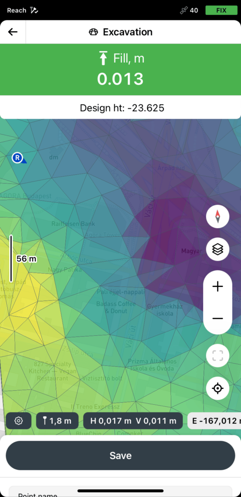
For grade checks, Emlid Flow 360 loads the LandXML design surface alongside the alignment. Once it’s in the project, every captured point shows its cut or fill in centimeters.
Checking invert elevations in real time
Once a pipe section is in place and bedded, the field engineer brings the RX2 to the pipe end or manhole opening, holds the pole on the invert (or as close as access allows), and triggers a point capture.
The point gets a description, segment number—and Emlid Flow shows it against the design value, cut or fill in centimeters.
If the invert is within tolerance, the field engineer logs it on the point itself—description, feature code, optionally a photo—stored with the coordinates and timestamp in the project file. The stakeout report pairs each verified invert with its design value and delta, and the office sees it all in Emlid Flow 360, in a browser, with every point and its metadata.
If it’s out of tolerance, the field engineer flags the point the same way before backfill. The office picks it up through the same sync.
When something’s off
A failed grade check is much cheaper to fix while the trench is open than after backfill.
The logged GNSS point is the documentation: a measured elevation, time-stamped, and exported to the office in the same coordinate system as the design.
The engineer notifies the foreman and the surveyor or project manager, and the conversation is concrete: “Section 12 reads 4 cm above design at the downstream end.”
From Emlid Flow, the data lands in Emlid Flow 360 within seconds—not at the end of the day. The decision to re-bed, adjust the next section’s slope, or escalate to the engineer of record happens while the crew is still on the pipe.
Related reading: Minimize construction site visits: how to support your field crew remotely
Stage 3: As-built documentation before backfill
The as-built is the most time-sensitive step in the whole job. On most public utility projects, it’s also non-negotiable—the jurisdiction requires a certified record before project closeout.
Once the pipe is bedded and verified, the crew is ready to backfill. The trench closes, the equipment moves to the next station, and whatever wasn’t captured in those few minutes is gone, buried under compacted material that nobody will dig up to verify.
Conventional practice handles this with tape measurements and field sketches: a crew member measures from the offset stakes, writes the offsets and elevations on a worksheet, and the office digitizes the result later.
It’s faster than calling a survey crew back, but the result is only as accurate as the tape and the sketch. Lateral connections are the usual weak spot, most get an approximate offset rather than a real measurement.
What to capture and how to code it
Before backfill, the crew sets up the Emlid Reach RX2 and captures every feature that trades or maintenance teams will need to find later, using the survey codes library. The RS4’s IMU-based tilt compensation is particularly useful here—around an open trench, holding the pole perfectly level isn’t always possible, and the receiver compensates automatically without slowing the crew down.
- Pipe centerline points collected at regular intervals along the run.
- Invert elevations at each manhole and at every change in direction or grade.
- Lateral connections, including the connection point at the main line, offset, and depth.
- Manhole rim elevations and invert elevations.
- Bends, fittings, valves, and cleanouts.
The crew can attach a photo to any point—during point collection, linework, or stakeout. Photos go in from the app’s camera or the phone’s gallery, and save with the point data.
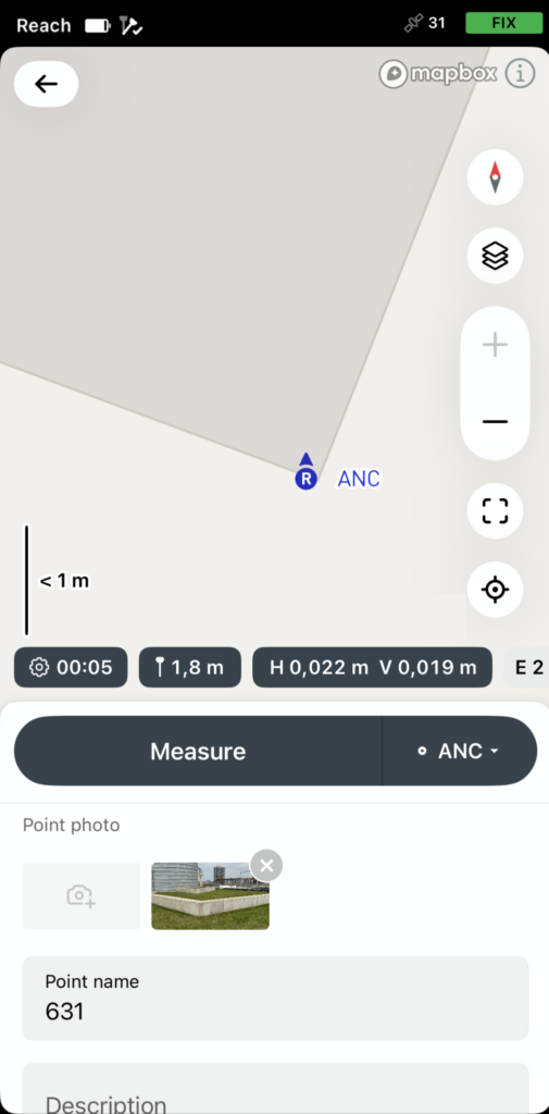
For as-built work, photos answer the questions that coordinates alone can’t. The office gets the coordinates, the code, the attributes, and an image of what’s actually in the trench.
Two weeks later, a question about which way a cleanout was rotated, or whether the lateral coupling matched the spec, gets answered from the photo. No return trip.
Notes from our Community: Improve your as-built workflow with point photos attachment in Emlid Flow
Getting data to the office before backfill is done
Digital field capture often hits an end-of-day bottleneck: the field team exports the project, sends it to the office, and the office imports the data into spreadsheets or CAD. By the time anyone spots a discrepancy, the trench is buried.
Emlid Flow 360 closes that gap. Each captured point or line syncs in the background as the crew logs it, so the office sees the as-built data the moment the run is done.
If something looks off—a missing feature, an out-of-spec invert, a coordinate that doesn’t tie into the existing manhole—the office can flag it before the foreman tells the operator to backfill.
For offices that don’t use Flow 360, the project exports as DXF for CAD or CSV for spreadsheets, with the design’s coordinate system and feature codes intact. Exports can also be partial—the upstream half of a pipe run, for example—so the field crew can share work mid-job without re-exporting the whole project.
Putting it together: one setup for all three stages
RTK GNSS delivers centimeter accuracy regardless of the stage, sometimes tighter than the work strictly needs, never looser:
- Layout works to the tolerance the design specifies.
- Grade verification leans hardest on vertical accuracy, since the question is whether the invert sits at the design elevation.
- The certified as-built has its own threshold, set by the jurisdiction’s record requirements. RTK with a base-rover setup fits all three.
The crew structure that goes with this is leaner than a traditional setup:
- The licensed surveyor handles the layout and the certified as-built where regulations require it, but doesn’t have to be on-site for grade checks during installation.
- The field engineer covers the day-to-day grade verification and routine as-built capture.
On smaller projects, both roles can be the same person. On larger ones, they’re separate, but they share the kit.
GNSS removes the bottlenecks that have historically forced teams to choose between speed and documentation, between waiting for the surveyor and skipping a check, and between sketching the as-built fast and getting it right.