Managing cut and fill: a field guide to grade control using Reach receivers and Emlid Flow
Grade checks are fundamental to construction. Before any structure goes up, the ground has to match the design—building pads, road alignments, drainage channels, utility trenches.
That means calculating where soil or other bulk material needs to be removed and added, then executing those movements accurately. Get it wrong and the costs compound: over-excavation, excess material, rework.
This guide covers grade control across common construction workflows, from topographic layout to as-built verification, using Emlid Reach receivers and Emlid Flow. From the surveyor to the site superintendent, any crew member can get to work with no special training required.
What grade control means in practice
Grade control means managing cut and fill in real time—keeping excavation and placement within tolerance of the design surface throughout the job. What actually drives the work is conformance, measured as the deviation between the constructed surface and design intent within the tolerances the application demands.
Those tolerances vary significantly depending on the use case. A parking lot with a 1–2% cross-slope sheds water, so bulk grading to ±2–3 cm is enough to hold it. A gravity sewer lives or dies by consistent pipe slope and invert elevation—too flat and it won’t flow, too steep and it scours. Agricultural land leveling for flood irrigation can require ±1 cm across an entire field because uneven ground leads to uneven water distribution and crop loss.
The shape of the problem changes by application, but the underlying need is always the same: fast, reliable elevation control and a clean record of what was actually built. Below you can find some more examples:
- Site development
Pads for commercial buildings, industrial facilities, and subdivisions. Large flat or contoured surfaces shaped to drainage and structural requirements. Volumes drive haul costs.
ㅤ - Roads and highways
Cut through hills, fill across valleys, subgrade prep for asphalt or concrete. Long linear alignments with steep cuts and high fills. Machine control is common on bigger jobs.
ㅤ - Utility construction
Trenches for sewer, storm, water, and drainage lines. Narrow, deep, and unforgiving on slope and depth. Often, the bottleneck is on a wider project.
ㅤ - Agriculture
Land leveling for flood-and-furrow irrigation. Tight elevation tolerances over large areas; GNSS-guided systems are now the norm.
ㅤ - Mining and quarrying
Bench cuts, overburden stripping, haul-road grading, stockpile management. Constant volume tracking.
ㅤ - Landfills, dams, and levees
Bulk earthworks with strict elevation, slope, and compaction requirements, verified at multiple stages.
ㅤ - Sports fields and golf
Contoured surfaces shaped for drainage and play. Subtle grade work over large areas.
In every case, the core question is the same: at this point on the ground, how much soil moves, and in which direction? Answering that accurately and continuously is what keeps excavation on target and rework off the schedule.
Related reading: Zero rework: how construction subcontractors win with GNSS
How crews used to do it
The traditional toolkit is stakes, string lines, grade rods, and laser levels—checked by a survey crew at intervals. It works on small, flat, straightforward jobs. On anything longer, deeper, or faster-moving, the friction adds up.
Stakes get knocked over by traffic, equipment, and weather. Grade checks happen at fixed points in time, not continuously, so errors only surface when someone measures—often after the damage is done. Laser levels need a line of sight and struggle with distance. Every design change means the surveyor comes back, which holds up excavation. As-built documentation ends up as a paper sketch and a phone call. These slow down the job and push rework into the schedule.
What changes with RTK GNSS
RTK (Real-Time Kinematic) GNSS combines a base and a rover to deliver centimeter-level accuracy. The base sits on a known point and continuously transmits its position and satellite observations to the rover.
The rover combines those with its own observations to compensate for atmospheric errors and calculate its position to the centimeter level in real time. Pair that with a field app that knows your design surface, and the rover shows you exactly how much to cut or fill at the tip of the pole anywhere on site, in real time.
In practice, that means you stop measuring after the fact and start measuring during the work. Existing-ground survey, layout, grade checks, and as-builts all run through the same kit. No separate workflows, no waiting on the crew.
Doing grade control with Reach receivers and Emlid Flow
Before the surveyor sets foot on site, the engineer develops the design surface—the finished grades, slopes, and elevations the site needs to reach. These come from the project drawings: road alignments, building pads, drainage plans, etc.
In design software, this is built and referred to as a DTM—Digital Terrain Model. In the field, the same model is simply called a surface: a 3D representation of elevations across an area that drives cut/fill calculations, grade checks, and stakeout. Different word, same data—the vocabulary shifts depending on which side of the workflow you’re on.
The surface is typically defined as a TIN (Triangulated Irregular Network)—a network of triangles connecting points with known elevations. TIN is a way of structuring surface data, not a single universal file format. While some software uses native surface-structuring methods, the actual file format can vary. In Emlid Flow 360, surfaces are supported in LandXML format.
Getting surfaces
There’s more than one way to build that surface:
- A conventional topographic survey produces the point data that the engineer uses to model.
- A total station, level run, or GNSS receiver gives precise spot elevations along a grid or at key breaks in the ground.
- LiDAR—either ground-based or mounted on a drone— captures dense point clouds that resolve fine terrain detail quickly across large areas.
Drone photogrammetry follows the same principle: fly a grid, process the imagery, and output a surface model.
For sites where speed and coverage matter, Emlid’s Reach RX2 receiver integrates with the PIX4Dcatch mobile app on LiDAR-enabled iPhones to capture 3D models at centimeter accuracy. The scans are processed directly in PIX4Dcloud or PIX4Dmatic, producing a surface that imports straight into Emlid Flow—no conversion, no extra steps required.
Changing the rules with the Emlid ecosystem
Traditionally, grade checks meant waiting—waiting for the survey crew to come out, set up, shoot the elevations, and confirm the excavation is on target. On a busy site, that’s a bottleneck. Equipment sits idle, the superintendent makes judgment calls, and errors surface too late to fix cheaply.
With Reach receivers, Emlid Flow 360, and Emlid Flow, that dependency no longer exists. The manager sets up the project once—coordinate system, design surface, codes, tolerances—and pushes it to the field. From that point, anyone on site can run a grade check.
The superintendent can walk the pad and see live cut/fill at the tip of the pole. The VDC team can verify that what’s in the ground matches what’s in the model. The foreman can confirm a trench depth before the pipe goes in. None of these checks requires survey training. The result is fewer delays, fewer callbacks, and a smaller window for expensive mistakes.
Step-by-step workflow
The complete workflow can be broken down into the following steps:
- Prepare the design surface and export it in LandXML format.
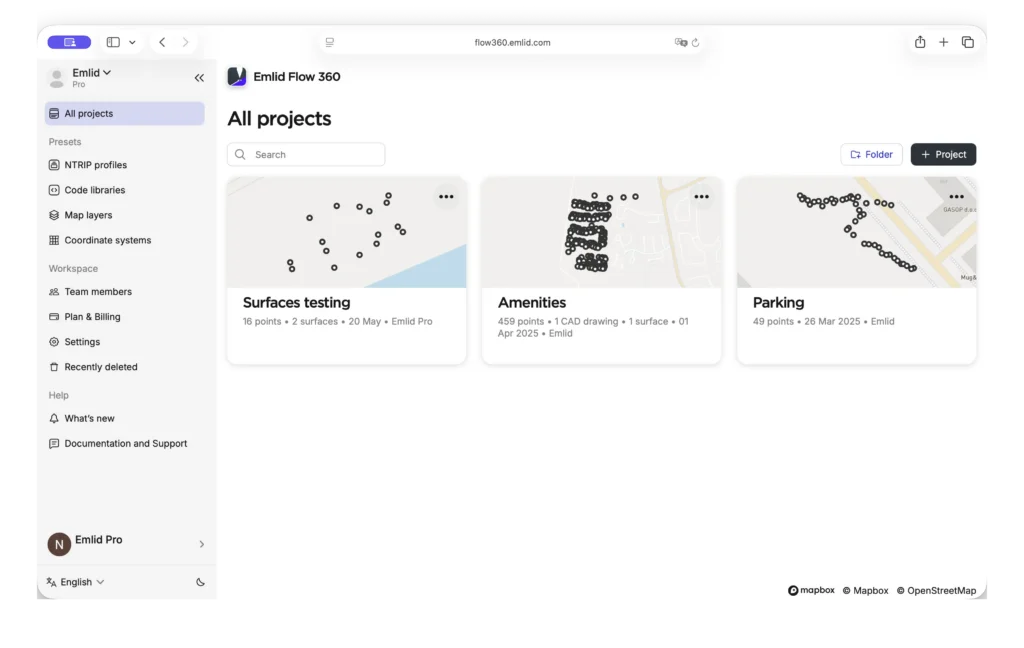
- In the office, sign in to Emlid Flow 360 with your Emlid account and set up the project:
- Create a new project in your workspace.
- Select the required coordinate system from the coordinate system library or import the localization parameters.
- Create and apply a code library, if needed.
- Import geometries in CSV, SHP, KML, or DXF format, if needed.
- Add map layers, if needed.
- Import the design surface.
- Invite field engineers to the workspace with the project you created.
- In the field, sign in to Emlid Flow with your Emlid account and open the synced project with the imported surface.
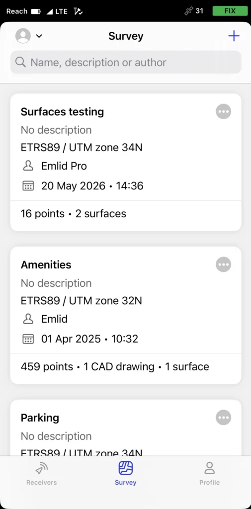
- Start staking out the surface or individual objects within it. If needed, you can also collect additional features during surface stakeout without switching workflows.
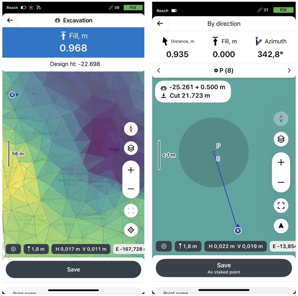
With the surface loaded, the Reach rover compares its live position against the design at any point on the site and shows the cut or fill value at the tip of the pole.
Where the workflow requires it, a vertical offset can be applied directly in the survey settings — useful when working against the same DTM at different stages of a project, such as subgrade before paving or rough grade before topsoil.
To ensure these cut-and-fill calculations are centimeter-accurate, the rover must first obtain centimeter-level positioning through RTK corrections.
To obtain RTK corrections, connect the rover either to a local base station or to an NTRIP correction service over a cellular network. In remote areas without reliable internet, or where you need full control of the setup, two Reach RS4 receivers working over LoRa radio is the practical choice.
For mixed fleets, the RS4 also supports UHF radio using the Trimtalk 450S protocol. Where cellular coverage is solid, Reach RX2 connects directly to the network provider’s corrections service and delivers the same centimeter-level accuracy in a much more compact package—no base station, no radio link.
Building pad on a commercial site
To put it in context, here’s how it plays out on a real job. A site contractor takes on a commercial building pad requiring roughly 2,500 m³ of cut and 1,500 m³ of fill. The crew creates a 3D model of the existing surface.
Back in the office, the engineer builds the design surface against that topo and exports it as a LandXML file. The project manager or VDC imports it into Emlid Flow 360, sets up the project, and pushes it to the field.
On the site, the Reach rover shows live cut or fill at any point across the pad. The dozer operator runs the bulk cut while the field crew member spot-checks every couple of passes. Over-excavation in two low corners gets caught early — before it needs extra fill to correct.
Once the pad is rough-graded, the crew shoots finished elevations across a denser grid and checks them against the design surface.
See how Emlid fits your site
Grade checks, stakeout, as-builts, topo verification — your crew can handle all of it without waiting on a survey team. See how contractors are using Reach receivers and Emlid Flow to keep equipment moving and rework off the schedule.
Tape measure vs. GPS in construction: when to upgrade your layout workflow?
Customer story: high-speed water infrastructure layouts and as-builts with Emlid
How to manage 10,000+ construction surveying projects and structure data at scale
QA/QC workflows in construction: a practical guide for your field crew